Defining Stretch Blow Mold Bottle Formation Parameters
A Paper on WheelWatcher™ Data by Greig S. Latham, P.E.
WheelWatcher is an integrated system used to gather critical blow mold parameters from production machinery in real time. WW executes several digital signal processing (DSP) algorithms to determine the quality of the every bottle produced. WW also makes this data available to interested personnel, statistical process control (SPC) programs and data archives. Depending on the activity involved these interested personnel can be from production, maintenance, research, development, engineering and quality control departments.
What follows is a summary of the critical blow mold parameters of interest and a discussion on the interpretation of various graphs provided by WheelWatcher™. The graphs presented were taken from actual production data.
These graphs are not intended to represent the WheelWatcher™ operator interface. These data are presented offline and in the context of analyzing the nature of stretch blow molding bottle formation. These graphs are, however, a subset of the views presented on the WW operator interface. Indeed, advanced WheelWatcher installations use more complicated regression, curve fitting and filters to provide other data valuable in research, development and quality control efforts.
The typical blow curve is presented first. This curve is followed by discussion on the pressure-related parameters and later by the displacement related parameters. Finally, parameters and views related pressure and displacement together are given.
Inasmuch as the bi-orientation of the material in plastic bottles is critical to their strength, the importance of velocity and acceleration of both the stretch rod and the blow pressure can not be understated. A great deal can be learned by observing both the slope and amplitude of these plots. Equally important in creating profiles used to detect bad bottles are the differences in absolute magnitude of the rapid excursions used to orient the bottle material.
While this document presents various graphs for a “good” bottle, the reader may be interested in similar views of data taken from “bad” bottles. WheelWatcher extracts several key ratios, indices and values from the data points sampled over a bottle formation cycle. Many times these results are used to characterize the results of the blow mold process and are used as discrimination factors to reject a bottle. For more information, please contact Keeva.
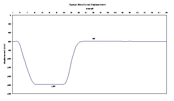
Typical Blow Curve
Perhaps the most popular WW graph is the one known as the blow curve presented below. The reason for its popularity is the intuitive nature of the presentation. It is immediately obvious that the stretch rod can be seen moving down to its fully extended position. During the downstroke, the low blow air is applied. With the stretch rod fully extended, high blow air is switched in to push the preform into the mold. With the high blow air applied, the stretch rod is retracted. After the bottle has cooled on the mold, the high blow air is exhausted in preparation for removing the bottle from the mold cavity.
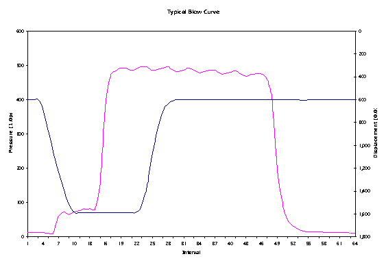
There are many production, maintenance and quality control related problems that can be detected by WW using this view alone. While this particular graph does not indicate any real problems, the following discussion shows how advanced algorithms can reveal more about the process.
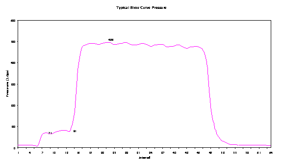
Pressure as a Function of Time
Radial orientation of the polymer chains help give the bottle it strength. This orientation occurs when the high blow air is applied. However, the entire pressure cycle is critical. The low blow air must be applied at precisely the right instant and in sufficient quantity and at the correct pressure to keep the preform from collapsing on the stretch rod as it extends. In the graphs that follow, the blow pressure is shown by itself as a function of time, in the first derivative and in the second derivative.
The bottle formation begins as the stretch rod starts down. With the stretch rod in motion, the low-pressure air keeps the preform from collapsing on the stretch rod as it stretches the material down inside the mold. When the stretch rod reaches the base of the mold, the blow pressure is switched to high pressure. The high-pressure acts to force the now stretched preform into the inside of the mold. The high pressure is held for an interval to allow the plastic material to cool as it is now in contact with the mold. The mold is chilled with process water to speed the cooling or curing process. Finally, the air is exhausted in preparation to extract the now completely formed bottle from the mold.
The critical pressure related parameters monitored by WheelWatcher are:
Minimum Low Blow Pressure
Minimum pressure recorded over the low blow interval.
This value is used to determine if sufficient blow air is available to keep the preform from coming in contact with the stretch rod during axial orientation. As the stretch rod moves down and elongates the preform would collapse on the stretch rod were it not for a cushion of air to billow or buffer the preform from the stretch rod.
If this value is less than the Minimum Low Blow Pressure Preset then
blow air is
not available
an open point exists is the blow air circuit
a valve problem exists
the preform has blown out
Maximum Low Blow Pressure
Maximum pressure recorded over the low blow interval
If the Maximum Low Blow Pressure exceeds the Maximum Low Blow Pressure Preset then
a three way valve has failed
the low blow pressure regulator is set too high
a neighbor’s three way valve has failed
an obstruction exists in the blow air circuit
Minimum High Blow Pressure
Minimum pressure recorded over the high blow interval
This value is used to determine if sufficient blow air pressure and volume is available to cause acceptable radial orientation of the bottle. After the stretch rod has reached it maximum extension the high blow air is applied to the preform. The high blow air forces the now elongated bottle into the inside of the mold cavity. The volume and pressure must be sufficient to force the material into intricate mold designs. When the preform material comes in contact with the mold, heat is lost and the material changes properties very quickly. If there is not enough radial velocity, the material will chill sufficiently to not allow proper bottle formation.
If this value is less than the Minimum High Blow Pressure Preset then
blow air is not available
an open point exists is the blow air circuit
a valve problem exists
the preform has blown out
Maximum High Blow Pressure
Maximum pressure recorded over the high blow interval
If the Maximum High Blow Pressure exceeds the Maximum High Blow Pressure Preset then
the high blow pressure regulator is set too
high
an obstruction exists in the blow air circuit
Pressure Reference
Minimum pressure recorded over the entire interval
If the Pressure Reference exceeds the Pressure Reference Preset then
the transducer is not calibrated
a valve failure is constantly applying blow air to the air circuit
blow air is trapped in the air circuit
noise is being induced in the transducer wiring
High Pressure Bypass
![]()
Difference between Maximum and Minimum Low Blow Pressure
In the event of a three-way valve failure this value exceeds the High Pressure Bypass Preset
Shut-In Pressure Drop
![]()
Difference between Maximum and Minimum High Blow Pressure
This values gives and indication of the air pressure leakage that occurs while the bottle is being cooled. With high blow air applied to the bottle a leak may occur at the o-ring seal or another place in the air circuit.
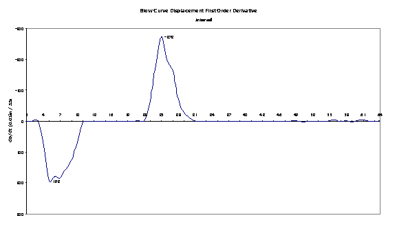
Pressure First Order Derivative or Velocity
As radial orientation is important to the strength of the bottle, the first order derivative plot is the domain used to determine the success or failure of the process to correctly form the bottle. Considering the pressure velocity plot below, it is clear the low blow velocity is much lower than the high blow. It is also easy to see the exhaust or depressurization velocity is less than the high blow or pressurization velocity. This makes sense, as there is a great deal of pressure behind the pressurization action, while depressurization simply exhausts to the ambient atmosphere.
One would think the low-pressure velocity is not so important as the high-pressure velocity since the low-pressure charge serves to keep the preform off the stretch rod as it extends. However, insufficient low blow air can ruin a bottle before it has an opportunity to be oriented axially or radially. Obviously, the high-pressure charge is important because it is used (with the stretching action) to align the polymer chains and give the bottle its rigid properties.
By observing the plot, one can see that if it became important to gain cycle time during the exhaust phase, a negative pressure or vacuum could be applied to the exhaust port. The actual time spent in low blow, high blow or exhaust can be determined by subtracting the zero velocity crossing time at the beginning of the action from the zero velocity crossing time end of the action.
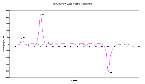
The symmetry in this view is a direct indication of the stability of the blow process during the formation of this bottle. Deviations in the blow process show up readily in this view and in the acceleration view.
WheelWatcher parameters used in the velocity domain are:
Low Blow Velocity
Maximum blow velocity detected over the low blow interval.
This value gives a direct indication of the ability of the air system to keep the preform from collapsing on the stretch rod during axial orientation.
High Blow Velocity
Maximum blow velocity detected over the high blow interval.
This value gives a direct indication of the radial orientation process.
Blow Pressure Ratio
High Blow Velocity divided by Low Blow Velocity.
![]()
This ratio is used to ensure the preform is not overly stretched radially during stretch rod extension. Too low a number indicates that too much radial orientation may be occurring during stretch rod extension rather than after axial orientation has finished.
Blow Spread
Absolute value of the High Blow Velocity less the Exhaust Velocity
![]()
If this spread is too great there is too much disparity between the inlet and outlet of the air circuit.
Exhaust Ratio
Exhaust Velocity divided by High Blow Velocity.
![]()
Normalized by the high blow velocity, this measure of exhaust performance provides a relative indicator of the exhaust process.
Exhaust Velocity
Maximum blow velocity detected over the exhaust interval.
This value is a direct indication of the ability of the station to get rid of blow air prior to bottle extraction.
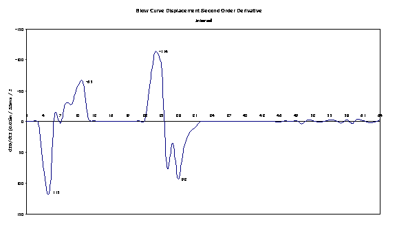
Pressure Second Order Derivative or Acceleration
Because of the symmetry of the first order plot, the second order plot is likewise symmetrical. This plot simply reinforces the earlier observations about the pressure activity. If there were a problem or an anomaly, however, it would show up quite dramatically in the view.
Trending the acceleration provides an indication of the air circuit’s ability to carry sufficient air to the bottle during the blow interval. Real time data can be integrated over time and compared with mold cavity volumes to ensure enough air is being used to form the bottle without relying on air flowmeters.
WheelWatcher derived acceleration parameters are given below.
Low Blow Attack Ratio
Peak Low Blow Acceleration divided by Peak Low Blow Deceleration.
![]()
This ratio allows quality tracking for a parameter that should remain near unity. Any asymmetry in the blow acceleration over this interval indicates a serious blow air problem.
High Blow Attack Ratio
Peak High Blow Acceleration divided by Peak High Blow Deceleration
![]()
This ratio allows quality tracking for a parameter that should remain near unity. Any asymmetry in the blow acceleration over this interval indicates a serious blow air problem.
Exhaust Attack Ratio
Peak Exhaust Acceleration divided by Peak Exhaust Deceleration
![]()
This ratio allows quality tracking for a parameter that should remain near unity. Any asymmetry in the blow acceleration over this interval indicates a serious blow air problem.
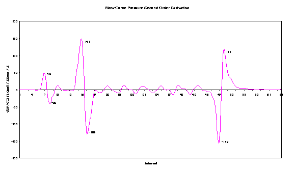
Combined Pressure P(t), dP/dt and d2P/dt2 Curves
Once familiar with the blow curve, the various pressure plots and the blow mold parameters involved it is helpful to view the different views together. In the graph below, the instantaneous pressure, velocity and acceleration are shown synchronized in time. This view is especially helpful in visualizing the relationships between curves.

WheelWatcher uses the velocity and acceleration data to determine and validate the start of the low blow, high blow and exhaust interval. It is much more reliable to use zero crossings that to use instantaneous data values and compare them to threshold values to determine the start of an interval. WheelWatcher also correlates the pressure intervals with the displacement intervals to ensure the two are properly synchronized in time.
Displacement as a Function of Time
The graph below repeats the displacement graph as a function of time as shown on the first, combined plot. In this view, the pressure curve has been removed to improve the clarity. The displacement curves are used to measure the effectiveness of the axial orientation of the bottle.
The stretch rod extends to push or stretch the preform to the bottom of the mold. Once there, the stretch rod holds the preform down near the mold bottom to allow the high-pressure air to form the bottle. Once the high pressure has been applied, the bottle has cooled to the point where it is rigid. The stretch rod then retracts and the bottle continues to cool since the high pressure holds the bottle against the water-chilled mold. With the stretch rod out of the way, the high-pressure air is exhausted and the bottle is removed from the mold.
It is not obvious, but on close examination a slight bump can be seen in the extension interval. Compare how readily apparent this bump or jerk is in this view compared to the velocity and acceleration curves.
All aspects of the stretch rod motion are apparent in these views. This graph shows a normal retraction; many graphs show a delayed retraction as a result of improperly adjusted cylinder exhaust ports.
WheelWatcher provides the following displacement related parameters:
Minimum Stretch Displacement or Displacement Reference
Minimum displacement recorded over the non-axial orientation interval
If the Displacement Reference exceeds the Displacement Reference Preset then
the transducer is not calibrated
a mechanical problem exists
noise is being induced in the transducer wiring
Maximum Stretch Displacement
Maximum displacement recorded over the axial orientation interval
If the Maximum Stretch Displacement exceeds the Maximum Stretch Displacement Maximum Preset then
the
transducer is not calibrated
a mechanical problem exists
noise is being induced in the transducer wiring
If the Maximum Stretch Displacement is less than the Maximum Stretch Displacement Minimum Preset then
the
transducer is not calibrated
a mechanical problem exists
noise is being induced in the transducer wiring
Displacement First Order Derivative or Velocity
In the first order derivative plot below, notice the obvious difference between stretch rod extension and retraction velocities. Also notice the obvious jerk of the stretch rod during the extension interval.
The first order derivative plot indicates the velocity. This plot, like all displacement plots, has the ordinate (y-axis) or displacement plotted in reverse scale. When the slope of the line is positive or downward the velocity is increasing. Conversely, if the slope is upward the velocity is decreasing. If the slope of the line changes during the downstroke as it does above, this indicates a jerking action during extension. The number of slope reversals is an indication of the smoothness of the motion. This could be vibration in the cylinder bearing or simply the stretch rod overcoming the resistance of the preform or preform as it is stretched. It is not uncommon to observe four or more jerks during extension of a stretch rod when everything is not running properly.
The magnitude of the dD/dt peak is an indicator of the speed of the stroke. In this case, the absolute value of the upstroke or retraction (-272) is greater/faster than the down-stroke or extension (193). This makes sense since it is easier to retract the stretch rod without resistance than it is to stretch the bottle during extension.
Ideally, the excursions on this plot should look like triangles. Obviously, this extension should be investigated or at least monitored closely for increasing problems. Often, there is a ripple seen at the end of retraction, indicating the aforementioned cushioning or braking action caused by the exhaust port setting.
Displacement parameters are:
Extension Velocity
Maximum extension velocity detected over the extension interval.
This value gives a direct indication of the axial orientation process.
Retraction Velocity
Maximum retraction velocity detected over the retraction interval.
Stretch Bilateral Resistance Ratio
Peak Extension Velocity divided by Peak Retraction Velocity
This ratio is an indication of the health of the stretch rod extension. The mechanical system can only move so fast. The retraction portion of the cycle should be the fastest. By normalizing the extension velocity by the retraction velocity the relative success or health of extension is clearly measured. Additionally, a properly heated preform offers less resistance to the stretch rod extension. Lower numbers indicate a labored extension and a direct indication of problematic extension.
Stretch Spread
Absolute value of the Retraction Velocity less the Extension Velocity
![]()
This value is a direct indication of the overall health of the stretch rod operation. Leaking seals or otherwise defective air cylinders are apparent from this value.
Retraction Settle Index
Elapsed time from maximum Retraction Velocity to first zero velocity or Displacement Reference.
![]()
Where the Settle Roughness Index indicates the smoothness, it is possible to constrict the stretch rod exhaust port so much that the stretch rod does not retract quickly enough. By using this index with the Settle Roughness Index, maintenance personnel can be sure the port is set properly.
Displacement Second Order Derivative or Acceleration
If the first order plot should ideally look like triangles, the second order plot should look like spikes in the direction of the slope of the triangle in the first order derivative. One can imagine these spikes laid over the plot below if only at the largest excursions are considered.
The magnitude of the excursions indicates the acceleration or how fast the velocity of the rod is changing. Once again, the plot should be uniform in the desired direction. The jerking of the rod can be seen even easier in this view. The number of slope sign transitions divided by two between the adjacent minimum and maximum are the number of times the rod accelerated or decelerated over that interval. During both the extension and retraction, once such jerk occurred. During retraction there were really no such jerks. It is very obvious that between extension and retraction there were no surprises as the acceleration was zero (0). This would not be the case in the instance where the center rod was lifted up by the high-pressure blow. WW has trapped this phenomenon and the results are dramatic in this type view.
Extension Roughness Index
Number of acceleration sign reversals between the onset on stretch rod extension and maximum Stretch Displacement.
![]()
This value indicates the amount of jerk or vibration during stretch rod extension. As the stretch rod cylinder overcomes the resistance of the preform there is some surging or plugging as the air pressure builds in the cylinder and overcomes the static coefficient of friction in the cylinder, bushings and even in the preform.
Retraction Roughness Index
Number of acceleration sign reversals between the onset on stretch rod retraction and Stretch Acceleration Reference
![]()
The retraction movement should be smooth. Normally, there are no significant friction forces to overcome. However, in the event of mechanical misalignment or binding, this index can be used as a predictive maintenance indicator.
Extension Attack Ratio
Peak Extension Acceleration divided by Peak Extension Deceleration
![]()
This ratio is an indication of the aggressiveness of stretch rod extension. As the air cylinder moves, the volume increases exponentially while the extension increases linearly. The stretch rod should speed up faster than it slows down. Also, the nature of the preform at it initial state is very different than when elongated. This ratio is another measure of the health of the extension function.
Retraction Attack Ratio
Peak Retraction Acceleration divided by Peak Retraction Deceleration.
![]()
This ratio is an indication of the aggressiveness of stretch rod retraction. As the air cylinder moves, the volume decrease exponentially while the retraction proceeds linearly. The air must escape through an adjustable orifice. The stretch rod should speed up faster than it slows down. This ratio is another measure of the health of the retraction function.
Combined Displacement D(t), dD/dt and d2D/dt2 Curves
In this view all three displacement curves are shown together. This presentation is especially helpful in visualizing the relationships between curves.

Notice the subtle "shallowing" of the D(t) plot toward the end of extension. The resulting change in velocity and acceleration is seen clearly. The steep, initial displacement shows up as a sharply rising velocity as evidence by the acceleration curve. During the first part of the extension all three traces are very similar. The rods then slows and jerks once. Finally it speeds up once again and then suddenly stops as it reaches full extension. It is not known whether the resistance of the preform or mechanical properties of the cylinder caused this shudder.
It is helpful to keep this plot available when considering each parameter separately. By comparing each parameter to the other, greater insight can be gained. The plots are synchronized in time to facilitate this comparison.
Combined Displacement and Pressure First Order Derivatives
Often it is interesting and helpful to view the pressure and displacement velocities together. Just as viewing the instantaneous data together in the blow curve provides insight in to the process, so does this view.
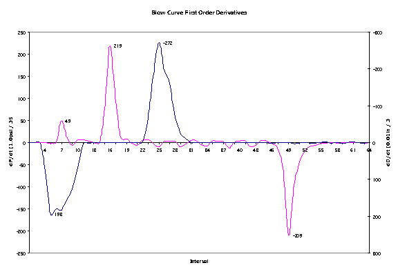
Perhaps the most interesting part of this graph is to consider the orientation of the preform. In this view we can see the crispness and symmetry of the stretch rod extension (axial orientation) and the high blow (radial orientation).
Another interesting observation in this view is the temporal relationship between the low blow and the stretch rod extension. In the graph above the low blow reaches its peak velocity at the same time the stretch rod achieves its maximum velocity.
The relationship between the timing of the high blow related to the speed (and therefore, position) of the stretch rod is readily apparent.
It is helpful to keep this plot available when considering each parameter separately. By comparing each parameter to the other, greater insight can be gained. The two plots are synchronized in time to facilitate this comparison.
This view introduces a combined critical parameter used to measure bottle formation:
Bi-orientation Index
Presented as a compound value of the Extension Velocity “by” the High Blow Velocity; for example, 193 by 219 or 193X219. The Bi-orientation Index highlights the quickness with which bi-orientation. The BOI together with the BOAI, presented next, are the two most general indicators of the bottle quality.
Combined Displacement and Pressure Second Order Derivatives
One can also tell a great deal about the process from the second order derivative shown below in the combined view.
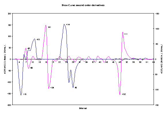
While this can be a busy view, the relationships between the onset, peak and completion of movements are valuable.
Another critical blow mold parameter comes from this view…
Bi-orientation Attack Index
Presented as a compound value of the Extension Acceleration “by” the High Blow Acceleration; for example, 115 by 141 or 115X141. The Bi-orientation Index highlights the quickness with which bi-orientation. The BOAI together with the BOI are the two most general indicators of the bottle quality.