Take a Test Article Library CEEJ Home Submit an Article Contact CEEJ
Article # 0031
Calculating ampacity in small-gauge, electrical cables
Greig S. Latham, P.E.
A
bstract-Guidance for predicting the ampacity of small-gauged conductors is not readily available and not addressed in the authoritative National Electric Code. While the Code and manufacturers provide definitive tables of ampacities, an analytical method is helpful. Increasingly, reliability and safety personnel are interested in ampacities of appliance and extension cords. The interest may be the result of product design, insurance, legal or forensic involvement. Because fire is a potential result, the First Law of Thermodynamics is an excellent starting point for a useful analytical tool. This paper explores one such analytical method derived as a result of a forensic engineering examination into the cause of a fatal fire.Index Terms- Ampacity, Current, Cables, Heating, Neher-McGrath, Thermal factors
I. INTRODUCTION
EXTENSION cords have fairly recently begun sporting a seemingly increasing number of rather durable tags. While most users could not be bothered to read the warnings contained on the tags, insurance companies and the U.S. Consumer Product Safety Commission no doubt wish more users would read the tags. The valuable information on the tags is borne of good science and the fact that too many users take too much for granted.
Much of these new warnings have to do with the ampacity or current carrying ability of the cords. Extension cords that are covered or coiled can start fires, even when not carrying rated current. This paper investigates this self-heating effect of a current carrying conductor insulated in a typical 'consumer-like' manner.
II. NEC & The Table
The authoritative source for wiring and methods is the National Electric Code (NEC). Article 400 in the NEC details the prescription for allowable ampacities of a wide variety of cords and cables. The warning tag on a #16AWG, 50 foot light-duty extension cord lists its ampacity at 13A. NEC Table 400.5 confirms the ampacity for this type cable is 13A. Whence comes this specification? The source will not be found in the Code, it's Fine Print Notes (FPNs) or any readily available trade information. To verify this claim, the reader is encouraged to perform a quick (or even exhaustive) literature or Internet search.
III. Neher-McGrath
The motivation for much of the NEC is fire prevention; therefore, it is logical that the restraint on ampacities is motivated by the effort to prevent fires when cables or conductors are in use. NEC Article 310 addresses ampacities for conductors in general wiring. This article has tables similar to those in Article 400. For example, Table 310.16 lists ampacities for not more than three insulated, current-carrying conductors in a raceway, cable or earth. Article 310 (C) states that "under engineering supervision, conductor ampacities shall be permitted to be calculated by means of the following general formula"
where:
| I | conductor ampacity (kA) |
| TC | conductor temperature (ºC) |
| TA | ambient temperature (ºC) |
| ΔTD | dielectric loss temperature rise (ºC) |
| RDC | dc resistance of conductor at temperature TC (μΩ/ft) |
| YC | component of ac resistance resulting from skin effect and proximity effect |
| RCA | effective thermal resistance between conductor and surrounding ambient (cm°C/W) |
Fortunately, a FPN directs the reader to "Annex B" for examples of formula applications. Unfortunately, in a self-contradiction, when the reader arrives in Annex B, there are no example formula solutions; instead, the examples take data from more tables.
Annex B does, however, present some hope by referring the reader to "the basic ampacity paper, AIEE Paper 57-600, The Calculation of the Temperature Rise and Load Capability of Cable Systems, by J.H. Neher and M.H. McGrath. After some effort, the explorer will learn that this paper is just about as difficult to find as the search encouraged earlier - even for an IEEE member. If all this indirection were not disconcerting enough, all of the NEC references to the use of this formula are for conductors buried in earth or concrete. Certainly there is no help for the analysis of an insulated extension cord in a residential setting.
Common sense indicates that much is missing from this formula in order to apply it to an extension cord buried by a stack of towels. Such considerations might include the radial dimensions of the cable insulation and the unit length considered. Left alone, then, to apply the formula, what might it look like? Thankfully, its likely ∆TD (dielectric loss temperature rise) will not change appreciably in the considered case. Likewise, YC (component of ac resistance resulting from skin effect and proximity effect) is negligible in the application example. So, the formula becomes
If the towel might ignite at 210°C and the ambient is 20°C, Annex B at least provides RCA for polyvinyl chloride (PVC) insulation at 650°C-cm/W. Chapter 9, Table 8 provides the dc resistance for the #16AWG conductor as 16.0Ω. A note to the table serves a reminder to adjust the resistance for temperature according to:
![]()
or,
![]()
![]() .
.
Now, since the formula is for microhms per foot and the current is in kiloamperes:
![]()
Assuming the formula has a significant safety margin built in (it does) and hoping no one asks for a dimensional analysis, this result is at least in the expected order of magnitude sufficient to give the engineer-turned-mathematician comfort if not confidence.
Besides a bias to thousands of Amperes in a big wire, it is reported the Neher-McGrath paper involves many factors, complex formulae and unusual units (some already experience here). The above result also indicates that Neher-McGrath is too conservative for consumer electronic applications (given Article 400 allowances). If fire is the concern, maybe there is another approach.
IV. First Law Of Thermodynamics
The first law of thermodynamics is a consequence of conservation of energy and states that a system may exchange energy with the surroundings strictly by heat flow or work. In other words, any change in internal energy must result from heat added to the system or work done by the system. Algebraically,
![]()
where:
| ∆U | change in internal energy (J) |
| Q | heat added (J) |
| W | work done (J) |
This conservation of energy also holds that heat added to a system equals the heat lost by the system. Viewing the First Law in this light provides a convenient framework for the analysis of self-heating in conductors.
Consider a 3m (~10ft) section of #16AWG copper, current carrying conductor insulated by 0.2m (~6in) or so of cotton material. What is the ampacity of this conductor?
For a wire, the heat lost to convection, radiation and the metal conductor is equal to the heat gained by solar and electrical heating, or,
Where (normalized for time):
| qc | heat, convection (W) |
| qr | heat, radiation (W) |
| qm | heat, metal (W) |
| qs | heat, solar radiation (W) |
| qe | heat, electrical heating, or copper losses (W) |
At low frequencies the radiation losses are negligible. Inside and protected from the sun, the heat gained from solar radiation is negligible. Therefore,

A. Convection Heat Loss
The convection heat loss (for a cylinder) is given by,

where:
| k | thermal conductivity, (cm°C/W) |
| A | Area, (m2) |
| dT | temperature change, (°C) |
| dr | radial increment, (m) |
with A=2prL, expanding and rearranging,
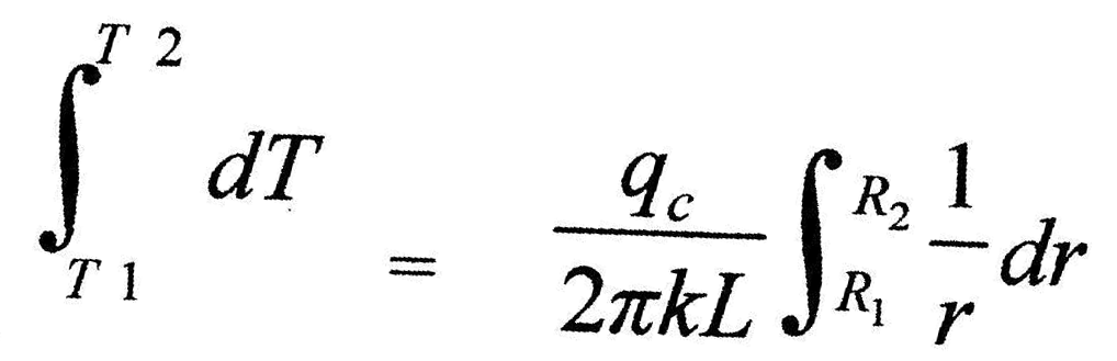 ,
(6)
,
(6)
which gives,
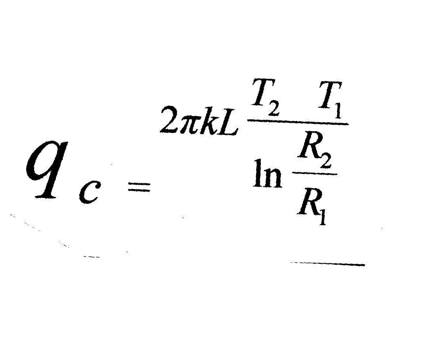
For cotton, k=0.0589W/cm°C [4], from NEC Table 8, the area (A) for #16AWG is 1.68mm², the ambient is 20°C, the ignition temperature of at least one type of cotton is about 210°C, from the inner surface of the cord (from NEC Table 8, the diameter=1.46mm) to the outside of the cotton (0.2m) and assuming a uniform thermal insulation,
or,

The PVC insulation of the conductor and the cord are thermal insulators that decrease the ampacity of the cable because the PVC thermal resistance would decrease the convection loss. For clarity, this added thermal resistance is not considered in the example.
B. Metal Heat Loss
The metal heat loss is given by,

where:
|
m |
mass, (g) |
|
Cp |
specific heat, (J/g°C ) |
|
dT |
temperature change, (°C) |
|
dt |
interval, (s) |
For the copper conductor, the mass is determined from the density (8.96g/cm³), the volume of the #16AWG wire is computed from the cross-sectional area (1.3mm²) over the application length (3m), the specific heat is 0.38J/g°C and the temperature rise over ambient is the same 190°C seen earlier. Now,
or,
![]()
C. Electrical Heat
The electrical heat added is due to losses in the copper and is given by,

where:
|
I |
current, (A) |
|
R |
resistance (Ω) |
The same NEC table lists the #16AWG wire at 16.4Ω/km. The thermal coefficient of copper is 0.00323 and the resistance at the elevated temperature (see equation 3) is given by
D. Combined Heat Equation
Now, from the simplified equation 4,
Dimensionally, a Joule per second is a Watt; therefore the dimensions are correct. As one would expect, the current is inversely proportional to the time the wire must carry the current. Solving for I yields,
The ampacity for 1s is
![]() .
.
The ampacity for 60s is
and the ampacity as time approaches infinity is
 .
.
However, all this was for one conductor and the neutral must carry the same current; therefore the ampacity would be about 11A.
The ampacity falls off rapidly with time because it is difficult to lose the heat through that much cotton. The formula also helps to understand why the wire can survive a lightning strike comprised of 15 dart leaders and return strokes taking 35ms each. This particular strike would last 525ms and the wire could handle 280A over that interval. With a longer strike or a higher impressed current, of course, the conductor will fail.
It is also interesting that the NEC doesn't count on many people piling a lot of clothes on an extension cord since they allow 13A; but, one can see how the value is derived (using a different thermal conductivity, for loosely laid cotton, could easily produce a 13A result).
V. Experimental Results
An extension cord is designed to provide temporary electrical power to locations not served by permanently installed electrical distribution system.
The use of an extension cord involves assuming responsibility for employing the cord in accordance with the instructions included with and attached to the cord, as well as common sense.
Some of the more common misuses of an extension cord included: permanent installations, outdoor exposure, exposure to water, subjecting the cord to overcurrent conditions, subjecting the cord to overload conditions, mechanical deforming the cord by pinching, coiling the cord and insulating the cord such that heat produced in the cord is not dissipated as designed.
The purpose of this test is to validate the principles involved in self-heating of current carrying conductors. Coiling the conductor and insulating the coils enhance the effects.
A. Design
A section of 1/2-inch plywood was placed on the concrete floor to simulate wooden sub flooring in a residence. A section of carpet was placed on the plywood. Approximately 3m (~10ft) of the middle portion of a #16AWG extension cord was coiled into five (5) coils of about 0.6m (~2ft) for each coil. A thermocouple was attached to one of the coils using two wire ties. The coils were placed on the carpet. A coverall garment was loosely folded and placed over the coils such that the coverall covered the entire coil arrangement. Another thermocouple was placed within the interior folds of the coverall garment.
A load of two space heaters, rated at 1320W and 1500W (~24A @ 120Vac), was connected to the extension cord and the cord plugged into an outlet. An increased load and coils were used in order to reduce the observation time since they are proportional.
B. Data
The data were recorded every 2 minutes. For brevity and clarity, uninteresting data are presented in 20-minute intervals (see Table 1).
TABLE I
Cord Temperature (Tcd)
| Time | TCD(°C) |
| 0 | 20 |
| 2 | 26 |
| 20 | 91 |
| 40 | 123 |
| 60 | 153 |
| 80 | 177 |
| 100 | 198 |
| 102 | 212 |
| 104 | 215 |
| 106 | 227 |
| 108 | 228 |
| 110 | 230 |
| 112 | 231 |
| 114 | 232 |
| 116 | 234 |
| 120 | 190 |
| 140 | 110 |
The resulting graph appears below.
Fig. 1. Temperature and temperature rise as a function of time. Note the rapid temperature rise followed by the more dramatic cooling after the parting arc opened the circuit. The first derivative provides a clear visualization of the heating and cooling rate.
C. Results
Inspection of the remains revealed charred clothing, charred carpet, melted insulation and electrically-arced conductors. Popping noises were heard at about 100 minutes, electrical arcing occurred about 2 minutes later. After another 12 minutes, sparks were produced that resulted in the parting arc that stopped current flow.
About 120 minutes after applying power, the outside of the coils had self-heated to over 232°C (450°F). At this temperature, the cord insulation melted or ‘sleeved’ such that ultimately one cord conductor contacted the other that led to a parting arc, which stopped further heating.
After loss of power, the cord and clothing temperatures dropped dramatically toward the ambient temperature.
D. Interpretation
Inspection of the remains revealed charred clothing, charred carpet, melted insulation and electrically-arced conductors. Popping noises (presumably bubbling thermoplastic insulation) were heard at about 100 minutes, electrical arcing occurred about 2 minutes later. After another 12 minutes, sparks resulted in the parting arc that stopped current flow.
The mathematical model fairly accurately predicted the life of the cord in the experiment. Several factors explain the difference: omitting the PVC thermal resistance, non-uniform insulation, coils lying on top of one another and lack of insulation on the sides of the cord are but a few.
The temperature increased linearly (see Figure 1) to the point where the sleeved conductor spring forces in the coil pushed the conductors to a short circuit. Near the end, as one would expect, the reactions became more rapid and more violent. The data plotted for the right-side axis in Figure 1 is the first derivative of the temperature; this rate of change presentation provides insight into just how violent the action was.
VI. Conclusions
Common sense indicates that a current carrying extension cord should not be coiled or insulated; consumer warning tags warn against coiling or insulating in the event there is no common sense available.
Calculating the ampacity of a relatively small-gauged conductor is more easily performed using the First Law of Thermodynamics than the difficult to obtain and difficult to understand Neher-McGrath treatise.
The thermodynamic approach correctly predicts the time-dependent nature of peak or surge currents and is therefore more useful than some other analysis techniques.
"National Electric Code", NFPA 70. National Fire Protection Association, 2002 Edition.
J.H. Neher and M.H. McGrath, "The Calculation of the Temperature Rise and Load Capability of Cable Systems", 1957.
Gerald C. Newton, "Understanding the Neher-McGrath Calculation and the Ampacity of Conductors", http://www.electrician.com/articles/ampacity.htm, January 2000.
Rohsenow, W. M. and Hartnett, J. P., "Handbook of Heat Transfer", McGraw-Hill, New York, 1973.
Greig S. Latham has designed, authored, installed and supported automation solutions in a wide variety of industries he holds a BSEE from Texas A&M University, Texas, 1982. Mr. Latham was an A&M Distinguished Military Graduate and was Honorably Discharged after twice serving as an Armor Company Commander. He currently provides forensic consulting services to System Engineering and Laboratories in Tyler, TX and is the Managing Director of Keeva, LC in Allen, Texas. Mr. Latham is a Senior Member of the IEEE.
Article # 0031 TEST QUESTIONS: Coming Soon
Take a Test Article Library CEEJ Home Submit an Article Contact CEEJ