Take a Test Article Library CEEJ Home Submit an Article Contact CEEJ
Article # 0018
Designing Extruded Plastic Profiles
by Mike May, P.E.
While molding parts using thermoplastics is widely understood, extrusion of thermoplastic into profiles is less formally studied and discussed. The purpose of this article is to highlight some basic concepts and offer the extrusion designer some guidelines for creating designs that can be extruded.
Profile extrusion lends itself to creating primarily constant cross section parts that are subsequently cut into finite lengths. The process offers the parts designer a wide variety of possibilities for design flexibility. Like any process, a few basic concepts can help the designer design parts that fulfill the design requirements and can be produced repeatedly and economically. As is often the case, a vision of what the extrusion process looks like will help the designer as she/he creates designs to fill a specific need.
1 Basic Description of Process
1.1 Melt Plastic, Shape Plastic into Part, Cool Part
Figure 1 Block diagram of extrusion line
In the extrusion process, it is typical to take thermoplastic materials in pellet or powder form, heat that material using electrical heat or frictional heat in an extruder until it is at least in a plastic state and then continuously push the material through a die that has openings that shape the material into the part that is desired.
The tool that forms the plastic material into a shape is typically called a die. This die has channels cut into it to force the plastic material into a desired shape - sometimes the desired shape is different than the part that is anticipated.
After the material is channeled into the desired shape, it exits the die - and then the fun begins.... As the material exits the die (it is called the extrudate at this point), some form of cooling is necessary - sometimes the cooling starts when the part is still in the die, but that is beyond the scope of this discussion.
Cooling can come in many forms, but we will limit this discussion to vacuum sized or calibrated systems and air template systems. These systems are designed to cool the extrudate into the desired part. The part goes through a multitude of variables as it is being cooled – many of these variables are very difficult to control.
Typically, the extruded part is pulled through the process by a belt puller and then is cut to length using a saw or other cutting device.
1.2 Materials
Materials typically used in extrusion are similar to those used in molding - except that, typically a material that will flow easily and fill molds nicely are often difficult to extrude. Profile extrusion lends itself to materials that exit the die in a very stiff state. This property is indicated by a variety of terms, including drape strength, melt strength, melt stiffness, etc. An indicator of melt viscosity that is commonly reported is the melt flow rate of the material. Materials that lend themselves to extrusion typically have melt flow rates less than 1 (fractional melt) while those that are good for injection molding typically exceed 8.
In many cases, materials that are easier to extrude into profiles are those that do not change phase (solid to liquid) in the heating process. These materials soften to the point that they can be formed into the desired shape, but don't actually melt. The major reason that this is desirable is because you don't have to take so much heat energy out of the part to cool it down (freeze from liquid to solid). On the other hand, materials that change viscosity dramatically with small temperature changes can require a large amount of die tuning or development in order to get consistent flow through the die.
Materials commonly extruded include PVC, ABS, Polypropylene, Polyethylene, Thermoplastic Elastomers, Polycarbonate, Aramids and many others. PVC is probably the prevalent material in profile extrusion because of its cost, ease of processing and room temperature physical properties.
2 Part Configuration
Extruded profiles require some attention in the design phase in order to create a part that can be consistently reproduced.
Profile extrusion also offers some advanced capabilities such as crosshead extrusion or coextrusion where materials with different characteristics are combined in the extrusion process to create a part that has the benefits of several parts combined into one. This form of combining materials has been used for decades.
2.1 Combining Multiple Materials
By using compatible materials, it is possible to combine two or more materials in the extrusion die to create a single part.
If this is done using two or more compatible thermoplastics running through two or more extruders connected to the die it is termed coextrusion. An example of coextrusion might be a weatherstrip used on a window. In this case, a flexible material is used in the sealing section of the weatherstrip and a more rigid mounting section.
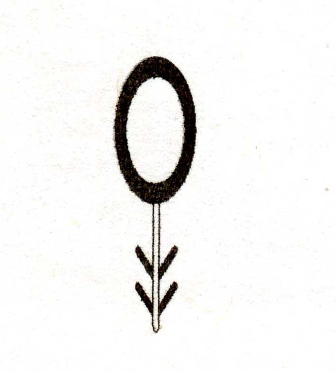
Figure 2 Coextruded Seal
Some design results that can be achieved using coextrusion include:
· Combining flexible sections for sealing with more rigid sections for mounting.
· Applying a thin layer of more expensive material over a less expensive core to achieve weatherability or color.
· Applying a thin layer of unfilled material over a filled material to get smoother, non abrasive surfaces.
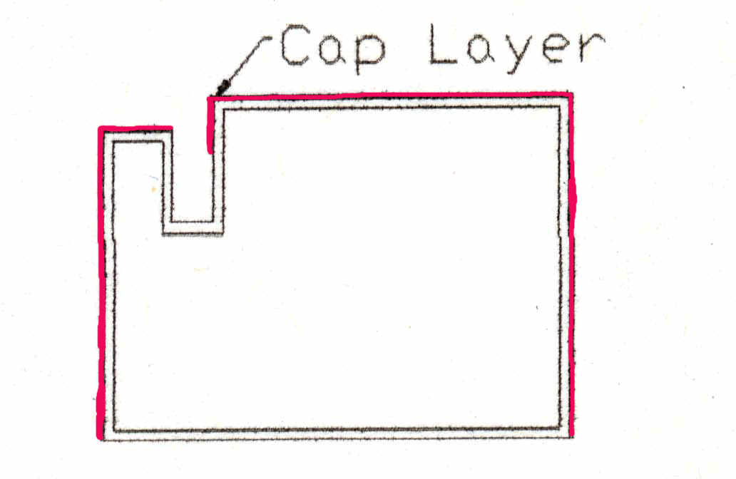
Figure 3 A thin cap layer can be used to protect substrate material.
· Applying sections with a different coefficient of friction for either more grip or easier sliding movement.
· Decorative patterns.
One thing that is very difficult to do is to coextrude a thin skin - or any detail inside of a thin groove.
If one or more of the materials is not run through an extruder, but is instead passed through the die and coated with or bonded to the extrudate it is called crosshead extrusion. Although it is not a profile, a great example of this process is an electrical wire.
Design results acheivable using crosshead extrusion include:
· Providing electrical contacts along the length of the part.
· Adding resiliency to a metal surface.
· Adding a bearing surface.
· Reinforcing a plastic structure.
Selection of materials for either of these processes is critical because the materials typically need to bond with each other when they are in contact with cold and pressure. In some cases, it is common for an intermediary material is used that bonds to both of the other materials. This material is called a tie layer.
2.2 Part Shape
The possibilities of what shape to extrude are virtually endless - but following some basic rules enhance the processability of the part and can dictate the cost of the finished product.
As in molding, maintaining an even wall thickness throughout a part can dramatically help processability. Envision a part which has two dramatically different wall sections:
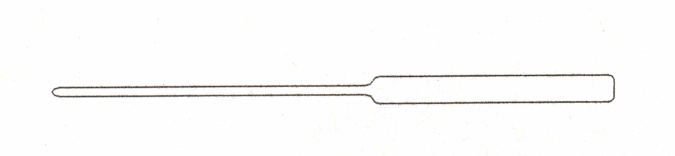
Figure 4 Example of uneven walls
We have talked about the fact that the material flows through the die and then exits into - basically air. Because the flow of the soft material through the die is not blocked at the end, all other things being equal, the material will take the path of least resistance - the thick sections and intersections. Material will flow much easier in this area, resulting in higher flow velocities causing almost no flow in the thinner sections. Die designers and developers have developed methods for handling this situation, but if it can be avoided, it makes the tooling cheaper and simpler.
Uneven wall sections or a part in which the center of gravity is significantly skewed to one side or the other will also cause problems with part straightness because the part will cool faster on one side than the other.
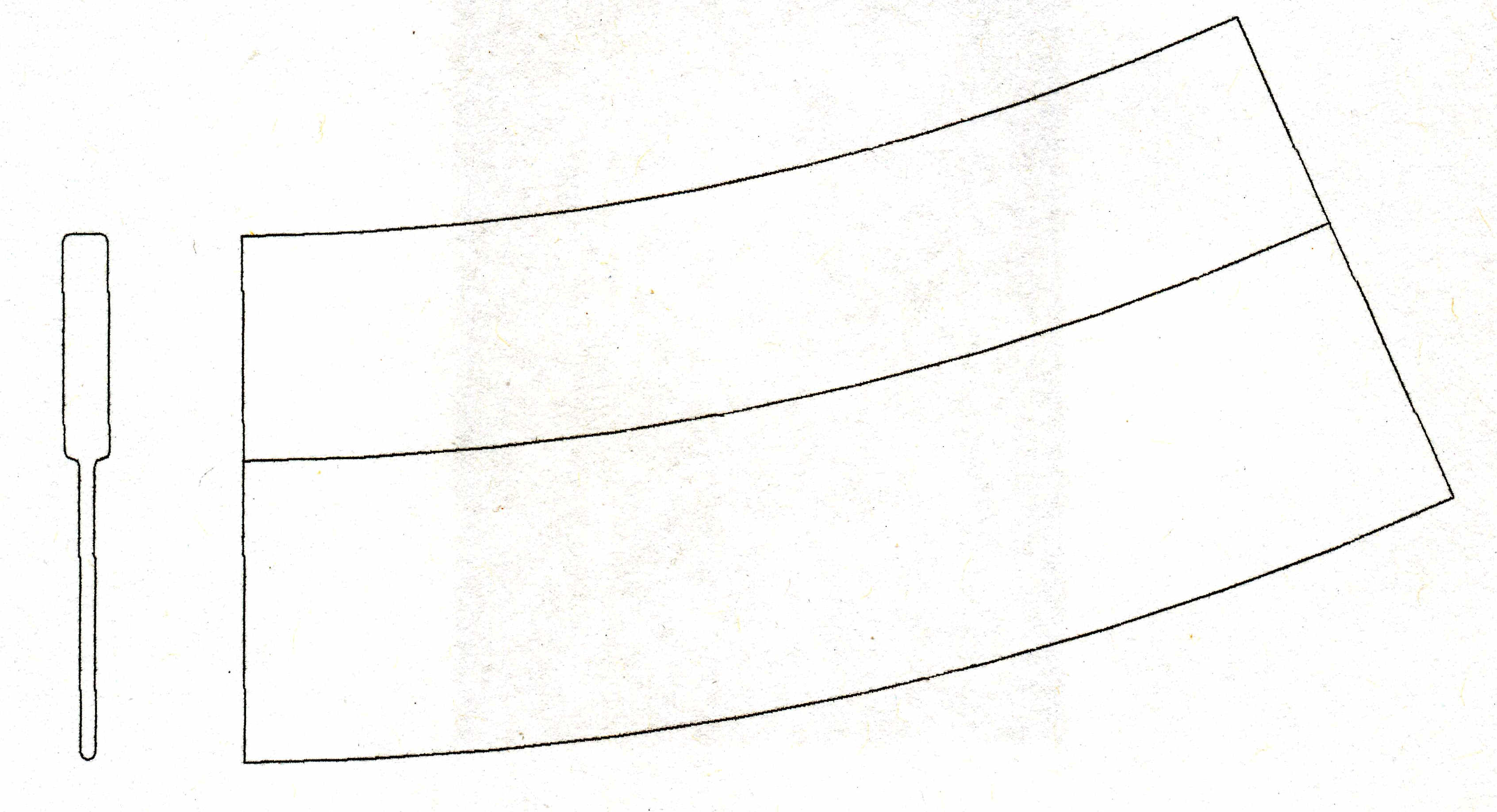
Figure 5 Bow can be induced by uneven cooling
Cooling challenges also arise when a part has a small opening that is relatively deep:
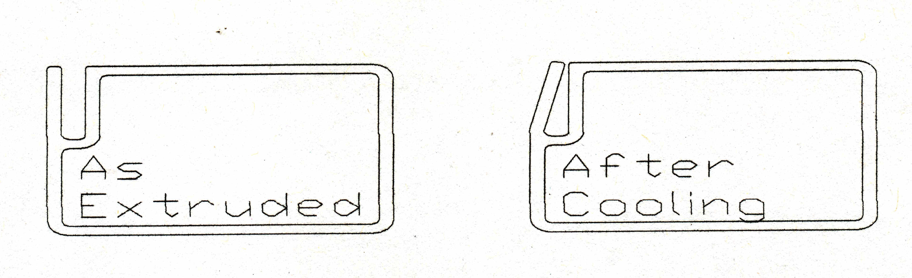
Figure 6 Part geometry can change with uneven cooling
In this case, it is difficult to cool the inside of the groove, and the groove will tend to close.
In all situations, it is important for the part designer to remember that the extrusion process is almost like two completely separate phases - the shaping of the extrudate and the cooling of the part once it leaves the die.
2.2.1 Hollows Versus Non Hollow
Hollow part designs - where there are areas of the part that no cooling can reach are well suited for cooling and shaping using vacuum sizing or vacuum calibration. In these cases, the part is run through a sizer or calibrator that is built to shape the outside walls of the part. This sizer can be mounted in a tank that can be flooded with water and a vacuum pulled on the whole channel – the atmospheric pressure on the inside of the part forces the outside walls against the sizers. In the enclosed tank, cooling is typically accomplished using the water in the tank and then drawn down through the vacuum source. Another form of vacuum calibration is to cut vacuum slots into calibrators and pull a vacuum directly on the part. In this case, cooling channels are often run in the sizer to put heat out of the part. This type of calibration can be done with no water contacting the part, or completely submerged in a cooling bath.
Vacuum calibration typically yields very consistent profiles with little variation from run to run. It can also provide for very smooth finishes on the outside surfaces. The cost of the calibrators can easily be more than the cost of the die.
One thing that vacuum calibration cannot do is control the interior walls of a hollow part. Those walls may be necessary for strength and there is a great temptation to try to apply fine details to those walls. Just remember - controlling those walls and the location and even shape of details in the interior is very difficult to do. If possible, limit critical geometry to the outside of the part. Interior walls should be about 2/3 as thick as the outside walls
Non-hollow part design - If a part does not have a hollow in it, and is made from an "extruder friendly" material, then in many cases we can eliminate the complexity and cost of vacuum sizing and use simple air or water templates. An air template setup is essentially a series of flat plates that runs through a bed of compressed air for cooling. While this method is relatively crude, tooling is inexpensive and good quality, functional parts can be made using it.
Design of a non-hollow part is relatively simple. Identifying the critical dimensions, maintaining consistent wall sections and using generous inside fillets will go a long way toward making a good extrudable part.
2.2.2 Wall Thicknesses
Rule number one with wall thickness - keep them the same if possible. If that is not possible, it is better to have the thin sections toward the end of the part - that is how the materials want to flow anyway.
Extrudable wall thicknesses are a function of the material for the most part. Most profile extrusions use wall thicknesses between .020 inches and .125 inches. Thinner walls can have problems with integrity and strength; extremely thick walls start having void issues - again depending on the material. In this case, the outside of the part freezes first, and the inside is still melted and shrinking - the interior material basically tears away from the rest of the material, resulting in a void - or an air pocket in the thickest part of the extrusion.
2.2.3 Specifying Dimensions and Tolerances
Designers of extruded parts need to recognize that there are a multitude of variables - many of them uncontrollable - surrounding the extrusion process. Actually most of these variables occur in the cooling of the part.
These variables create a situation where the final extruded part can vary from imperceptible changes. One extrusion veteran described a situation where the startup crew at an extrusion facility forgot to turn on the exhaust fans during startup and did not realize it until they had several parts up and "saving". The crew left the fans off until after their shift was over because they knew that as soon as they turned the fans on, the change in air currents would make the parts go out of spec - in this case, you could see the haze in the plant when the day shift came on - they had to turn on the fans and, sure enough all of the parts changed.
That being said, it is obvious that the part has to be defined in order to build tooling for it - today, that is done using CAD geometry, which means that every dimension does not have to be put on the print to define the nominal part. For extrusion production, critical dimensions for the parts should be identified and controlled and less critical dimensions should be listed as reference. Functional guages that check the function of the part are a great way to make sure that the part will function as desired.
Typical tolerances for an extrusion are +/- 0.020 inches for dimensions up to 1.5 inches. Tighter tolerances are possible where necessary, but they can increase tooling cost, set up time or run speed - or all three. In most cases, +/- .005 will be the tightest that can be effectively measured.
Lengths of parts also need to be considered. The type of cutting equipment and the length of the part will determine what tolerance is possible. Shrinkage of the part is another variable that has to be considered for long parts. Some materials show continuing shrinkage for several days after extrusion. A typical cut tolerance might be +/- .020 for relatively short parts cut using a flying knife. Longer and larger parts might require cut tolerances of +/- 0.250 inches.
2.2.4 Design Guidelines
Designing extruded parts is similar to designing other plastic parts:
· Consistent wall sections are preferred
· Minimum internal radii should be 0.030 or larger. Outside radii should be internal radius plus a wall thickness - if possible.
· Interior walls of a hollow profile should be about 60% the thickness of the outside walls.
· Details, such as screw bosses should not be located on interior sections.
· When joining two dissimilar materials, maximize intersecting surfaces.
3 Limiting Factors
The limiting factors for design detail, tolerance control, low cost or any other important aspect are related to:
· The size of the part - extremely small parts can be difficult to cool properly, resulting in slower run speeds or misshaped parts - in many cases, a very small part will cool differentially, causing thermally induced shape variation.
· Cooling - As the part cools, the thinner sections will cool first - the larger sections then cool, drawing the already rigid parts toward them. This can result in a bow down the length of the part or in openings changing shape as the part cools. If the part is complex, run speeds can be affected as you try to cool the part consistently.
· Extruder size - If the extruder is not matched well to the size of the part, slow run speeds or slow screw RPM's can result. A slow run speed increases cost of the part while slow screw RPM's can cause part variation or material inconsistency.
· Type of tooling - while a large volume part may justify expensive, complex tooling, many smaller volume parts can't. In the case of a high volume part, the customer may be willing to invest in this tooling in order to reduce the cost of the production parts. In many cases, run speeds and tolerances are limited by the use of less complex tooling.
· Material choices - low melt strength materials can be impossible to extrude, very crystalline materials can be difficult to cool and have many voids.
4 Conclusion
Parts made using plastic profile extrusion, on the surface are very easy to produce and the tooling is inexpensive. Like most things, there is more complexity here than meets the eye.
The extrusion process is less understood and has many more variables than injection molding. Some of the design concepts are similar, but in many cases transferring those concepts into reality takes a great amount of skill. Making smart decisions in the design phase improves the end result and reduces the cost of tooling and production.
Profile extrusion of thermoplastics offers the potential to combine different materials in the same part to bring specific characteristics to specific locations in the part. This process is can economically make parts of any length, from a fraction of an inch to many feet long.
Tooling for profile extrusion is typically less expensive than the tooling for an injection molded part. The process offers good functional geometry control, but typically has more variation than molding.
Mike May has worked for 20+ years in the profile extrusion
area. For 15 years he worked as the cheif part design/technical support person
for a $40 million a year plastic profile extrusion company. In the last 6
years, he has worked at GaMra Composites and has been responsible for part
design, tooling design, process development and any other hats that needed to be
worn in a small startup company.
Mike is a registered Professional Engineer and has bachelors degrees in
Mechanical Engineering and Engineering Management from the University of
Missouri - Rolla.
Title: Vice President
Organization: GaMra Composites, Inc.
Article # 0018 TEST QUESTIONS: Coming Soon
1. Profile extrusion lends itself to:
creating intricate and highly detailed parts without the need for secondary processing.
creating parts that are more durable and economical than injection molded parts.
creating primarily constant cross section parts that are subsequently cut into finite lengths
All of the above
2. Which of the following is a basic description of the profile extrusion process?
Melt the plastic, shape into a part, cut the profile to the required length and perform any secondary operations.
Melt the plastic, shape into a part, cool the part.
Force the plastic through a die, cool the finished part.
Melt the plastic, pour into a mold, cool the part.
3. Materials that lend themselves to extrusion typically have melt flow rates ...
greater than 8
greater than 1 (unity melt)
less than 1 (fractional melt)
greater than 50
4. In many cases, materials that are easier to extrude
change viscosity dramatically with small temperature changes.
do not change phase (solid to liquid) in the heating process.
do not have satisfactory properties at room temperature.
have a low molecular weight.
5. A design result that can be achieved using coextrusion is:
Applying a thin layer of unfilled material over a filled material to get smoother, non abrasive surfaces.
Applying a thin layer of more expensive material over a less expensive core to achieve weatherability or color
Combining flexible sections for sealing with more rigid sections for mounting.
All of the above
6. Which of the following is an important consideration in designing an extruded profile part.
Consistent wall sections are preferred
Outside radii should be as small as possible
Interior walls of a hollow profile should be about 200% the thickness of the outside walls
All of the above
7. Vacuum calibration typically ...
yields very consistent profiles
costs less than pressure calibration.
results in a poor surface finish
All of the above
8. Tooling for profile extrusion than the tooling for an injection molded part.
is typically less expensive
generally allows for finer details
has a shorter useable lifetime
all of the above
9. ______ is probably the prevalent material in profile extrusion because of its cost, ease of processing and room temperature physical properties.
Polypropylene
ABS
PVC
Polyethylene
10. Uneven wall sections or a part in which the center of gravity is significantly skewed to one side or the other will also cause problems with part straightness because ...
of the flow velocity differential across the part.
the material is still soft leaving the die.
the part will cool faster on one side than the other.
of voids created during the extrusion process.
Take a Test Article Library CEEJ Home Submit an Article Contact CEEJ